Robot Art Show
We were working on electricity and how that works. We used Arduino kits, designed a micro grid and so on which will be explained further.
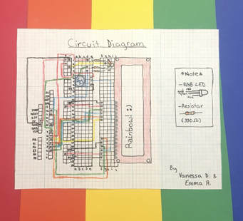
Circuit Diagram and video of project
Our circuit diagram includes different colors which wires connect to certain PIN numbers. The color of the wire doesn’t matter, it just looks better to have more color and matches with the rainbow. Also so it doesn’t get confusing.
|
This video is our project working. We spent more time in taking notes and trying to understand every single thing. We would’ve added music, but we couldn’t find a buzzer in time. Once we did, there wasn’t enough time to add it. Our project basically just says “Rainbow!:)” on the crystal screen and has a RBG LED flashing different colors. We decided not to add the buzzer because it was harder than it seemed and we couldn’t find one in time so we couldn’t do it. The frequency for the notes of a song is harder than it seems.
Coding for Arduino and notes
That is the coding for the arduino. The notes explaining what each thing means is after the // which is for notes.
Circuits and Electronics Info
We learned of two types of circuits. The series circuit and the parallel circuit. The series circuit is where the current must run through all the components one after another. The parallel circuit is a circuit with two or more pathways that the current can "choose" to go through. The current is the flow of charge through a circuit. A circuit is a complete loop of conductive material from one side of a power source (+) to the other (-). Voltage is the potential energy difference across a component in a circuit "drop" "push". Voltage equals current times resistance (V=ir, v is the symbol for voltage, i is the symbol for current and r is the symbol for resistance). Resistance is an obstacle in the circuit which slows down the current. For a series the r total equals the first resistance added to the second resistor and so on to the many resistors there are. For the parallel circuit the resistance will be 1 over resistance total equals the inverse of all the resistors in the circuit added together. The unit for voltage is Volts (V), the unit for current is Amperes also known as "Amps" for short (A), and the unit for resistance is Ohms (Ω).
Breadboards
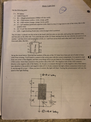
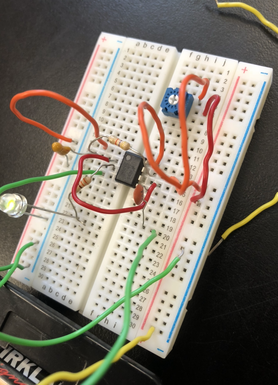
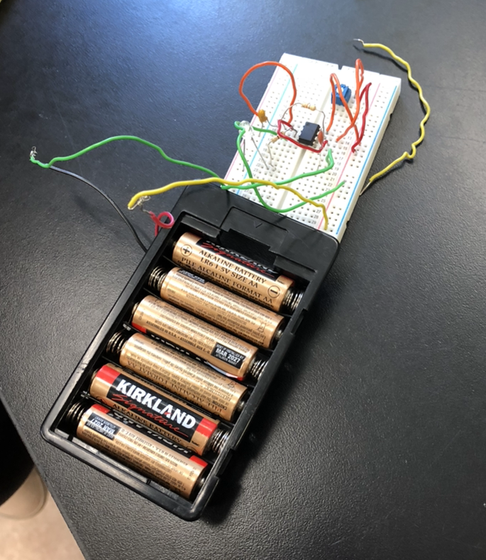
We worked with breadboards for this unit. We took a Blinky Light Quiz. We did everything correct, but for some reason it was not working. We worked in partners. The instructions are on the left and a picture of the breadboard set up to do the Blinky Light Quiz is on the right. The breadboards are a way of making connections and circuits in a small space and does not make it permanent.
We learned of two types of circuits. The series circuit and the parallel circuit. The series circuit is where the current must run through all the components one after another. The parallel circuit is a circuit with two or more pathways that the current can "choose" to go through. The current is the flow of charge through a circuit. A circuit is a complete loop of conductive material from one side of a power source (+) to the other (-). Voltage is the potential energy difference across a component in a circuit "drop" "push". Voltage equals current times resistance (V=ir, v is the symbol for voltage, i is the symbol for current and r is the symbol for resistance). Resistance is an obstacle in the circuit which slows down the current. For a series the r total equals the first resistance added to the second resistor and so on to the many resistors there are. For the parallel circuit the resistance will be 1 over resistance total equals the inverse of all the resistors in the circuit added together. The unit for voltage is Volts (V), the unit for current is Amperes also known as "Amps" for short (A), and the unit for resistance is Ohms (Ω).
Breadboards
We worked with breadboards for this unit. We took a Blinky Light Quiz. We did everything correct, but for some reason it was not working. We worked in partners. The instructions are on the left and a picture of the breadboard set up to do the Blinky Light Quiz is on the right. The breadboards are a way of making connections and circuits in a small space and does not make it permanent.
|
|
|
Power Novato
Wind Turbine Design
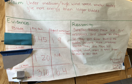
My group and I found out the last one which is small blades with a combination of a few (in our case, 4) blades works the best. We found out after testing 6 long blades and suddenly trying to do small blades with less number of blades and it worked better.
Electrical Fields
|
|
|
Basically the two tapes stick together or repel each other depending on how much electrons they each have and so on. Opposites attracts while sames repel. Electrons attract the protons and so on. The two forms above were questions I had to answer for each and I felt that it described what was happening in a way so I added it.
Electromagnet Lab
This explains our electromagnet and how it works along with what we used. It also explains what we were testing and what our results were.
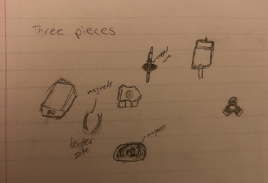
Dissect a motor
Magnetic field can lead to magnetic current using conductive material and a circuit in a way to create everything and get it to function and work using opposites attract and same repel and so on.
Our own Micro Grid for San Marin High School
There is more information on slideshow, this is just a summary. So for this micro grid we would power San Marin High School using Hydro power and solar. We would use solar panels and Hydro plants which the electricity for that will be from Stafford lake. It will all be connected by wires and there will be one power wall inverter which releases energy and 4 power packs which is the storage. The total will cost around $3,183,600.
Reflection
This unit was fun. Although there were a few problems that we had which was getting the blinky light quiz to work, we had everything right but it would not work. Maybe it was one of the components we used that didn’t work. Anyways, my favorite was the electromagnet lab and the robot art show. Although we did spend a lot more time on notes on the arduino than others which left us with less time on the project but overall I enjoyed the project. It was hard, but we finished it. I feel we shouldn’t have spent too much time on notes, but what is done is done and it was not all necessarily bad to have spent time on notes. The notes could be and are useful. A few things that went well in the project was I talked more than usual and we worked good together. We would switch the leadership role and have good cooperation and inputs of ideas. It was fun working with my group. We both did not understand most of it so we would help each other when we understood something and ask someone else. One thing is that we asked more questions and it has got me to learn to ask questions and not be too shy about it when asking other classmates. I know questions are great to ask and there is no wrong question to ask, but it is harder said than done. I have and started getting used to asking questions more which is good. We both worked a lot on the robot art show. The micro grid went well too, we all managed to finish it. I think the presentation went well and the overall product and project was great.
